
Custom Controller: Difference between revisions
From Project DIVA Addict
m →Outside Job: Added image |
m Added picture of completed custom home controller |
||
| (19 intermediate revisions by the same user not shown) | |||
| Line 1: | Line 1: | ||
[[File:Project DIVA Custom Controller Transparent.png]] | {| style="background-color: unset !important" | ||
| style="width:54%" | [[File:Project DIVA Custom Arcade Controller Transparent.png]] | |||
| style="width:46%" | [[File:Project DIVA Custom Home Controller Transparent.png]] | |||
|} | |||
=History= | ==History== | ||
<gallery mode="packed" widths="236" heights="500" style="float:right"> | <gallery mode="packed" widths="236" heights="500" style="float:right"> | ||
File:Project DIVA Arcade Transparent.png|Project DIVA Arcade was initially released in Japan on June 23, 2010. | File:Project DIVA Arcade Transparent.png|Project DIVA Arcade was initially released in Japan on June 23, 2010. | ||
File:Project DIVA Arcade Future Tone. | File:Project DIVA Arcade Future Tone.png|Project DIVA Arcade Future Tone was released November 21, 2013 and introduced the slider. | ||
</gallery> | </gallery> | ||
| Line 16: | Line 19: | ||
Project DIVA has been simultaneously available on portables, home consoles, and in the arcades since 2010. This arcade presence has influenced the home versions and vice versa. Project DIVA 2nd adopted the EXTREME difficulty and introduced the dual-wielding mechanism to deal with the requisite rapid button presses. Project DIVA Arcade: Future Tone introduced sliders after Project DIVA F introduced its scratch notes. | Project DIVA has been simultaneously available on portables, home consoles, and in the arcades since 2010. This arcade presence has influenced the home versions and vice versa. Project DIVA 2nd adopted the EXTREME difficulty and introduced the dual-wielding mechanism to deal with the requisite rapid button presses. Project DIVA Arcade: Future Tone introduced sliders after Project DIVA F introduced its scratch notes. | ||
=What Does This All Mean?= | <div style="clear:both"></div> | ||
==What Does This All Mean?== | |||
<div style="float:right;"><ul> | <div style="float:right;"><ul> | ||
| Line 33: | Line 38: | ||
On the home side of the equation, there are songs where button presses are fast enough to quickly tire out your thumbs if you try to single-wield the button presses. Using an arcade-like controller for the home games alleviates this stress. | On the home side of the equation, there are songs where button presses are fast enough to quickly tire out your thumbs if you try to single-wield the button presses. Using an arcade-like controller for the home games alleviates this stress. | ||
=Why Are These Controllers So Expensive?= | ==Why Are These Controllers So Expensive?== | ||
[[File:HORI Scalping on eBay.jpg|thumb|600px|The most expensive listings per HORI controller on eBay.]] | [[File:HORI Scalping on eBay.jpg|thumb|600px|The most expensive listings per HORI controller on eBay.]] | ||
| Line 45: | Line 50: | ||
If you’re looking to make your own controller to spite the high cost of pre-built commercial offerings, you’ll probably be spending more than if you just bought someone else’s controller. But if you’re building your own controller to spite the scalping, you can probably make out. | If you’re looking to make your own controller to spite the high cost of pre-built commercial offerings, you’ll probably be spending more than if you just bought someone else’s controller. But if you’re building your own controller to spite the scalping, you can probably make out. | ||
=What Do I Need?= | <div style="clear:both"></div> | ||
==What Do I Need?== | |||
==Tools== | ===Tools=== | ||
{| | {| | ||
| Line 174: | Line 181: | ||
|} | |} | ||
==Parts== | ===Parts=== | ||
{| style="width: 100%;" | {| style="width: 100%;" | ||
| Line 246: | Line 253: | ||
|} | |} | ||
==Paint== | ===Paint=== | ||
Painting is optional and purely cosmetic, but it can lend a professional look to your work. The main problem is time — you must wait for the paint to cure, and you definitely want to wet sand spray paint to get a smooth-as-possible finish. | Painting is optional and purely cosmetic, but it can lend a professional look to your work. The main problem is time — you must wait for the paint to cure, and you definitely want to wet sand spray paint to get a smooth-as-possible finish. | ||
===Spray Paint=== | ====Spray Paint==== | ||
{| class="wikitable" | {| class="wikitable" | ||
| Line 272: | Line 279: | ||
|} | |} | ||
===Cold Weather Supplements=== | ====Cold Weather Supplements==== | ||
Spray paint works best outdoors in warm weather. If you don’t have that luxury, you’ll need to simulate it. The best option is to utilize a ventilated upstairs room or finished attic. Place the parts to be spray painted near the ventilation point. Use heat lamps to heat up the paint, and let the ventilation pull the air across those parts. | Spray paint works best outdoors in warm weather. If you don’t have that luxury, you’ll need to simulate it. The best option is to utilize a ventilated upstairs room or finished attic. Place the parts to be spray painted near the ventilation point. Use heat lamps to heat up the paint, and let the ventilation pull the air across those parts. | ||
| Line 284: | Line 291: | ||
|} | |} | ||
==Game Control Parts== | ===Game Control Parts=== | ||
===Controller Board=== | ====Controller Board==== | ||
{| class="wikitable" | {| class="wikitable" | ||
| Line 310: | Line 317: | ||
|} | |} | ||
===Button Options (for L2/L1/Select/Home/Start/R1/R2)=== | ====Button Options (for L2/L1/Select/Home/Start/R1/R2)==== | ||
While the links aren’t the only options, they’re the ones that I feel make the most sense. Sanwa is the brand used in Project DIVA Arcade. Other brands are available, but they don’t offer any cost savings. On the off-brand side, color choice is limited and often come in bundles that mostly make no sense for this project. Seimitsu makes similar buttons — they only come in 7 colors but they might all that’s in stock when you go to shop. | While the links aren’t the only options, they’re the ones that I feel make the most sense. Sanwa is the brand used in Project DIVA Arcade. Other brands are available, but they don’t offer any cost savings. On the off-brand side, color choice is limited and often come in bundles that mostly make no sense for this project. Seimitsu makes similar buttons — they only come in 7 colors but they might all that’s in stock when you go to shop. | ||
| Line 330: | Line 337: | ||
|} | |} | ||
===EG Starts 100mm Push Buttons (PDFT/PDM39/PDMM)=== | ====EG Starts 100mm Push Buttons (PDFT/PDM39/PDMM)==== | ||
The EG Starts 100mm buttons come with springs that are FAR too heavy. I wouldn’t doubt if the spring was meant for joysticks, which are usually used for tension and provide a lot more resistance than button springs. You will need to shell out for set of button springs. | The EG Starts 100mm buttons come with springs that are FAR too heavy. I wouldn’t doubt if the spring was meant for joysticks, which are usually used for tension and provide a lot more resistance than button springs. You will need to shell out for set of button springs. | ||
| Line 342: | Line 349: | ||
|} | |} | ||
===EG Starts 60mm Push Buttons (All PS3 games + PDX)=== | ====EG Starts 60mm Push Buttons (All PS3 games + PDX)==== | ||
Again, EG Starts’ buttons come with springs that are FAR too heavy. | Again, EG Starts’ buttons come with springs that are FAR too heavy. | ||
| Line 355: | Line 362: | ||
|} | |} | ||
===Sanwa 100mm Push Buttons (PDFT/PDM39/PDMM)=== | ====Sanwa 100mm Push Buttons (PDFT/PDM39/PDMM)==== | ||
The Sanwa buttons come with 200g springs, but the bulb is sold separately. | The Sanwa buttons come with 200g springs, but the bulb is sold separately. | ||
| Line 367: | Line 374: | ||
|} | |} | ||
===Switch Options=== | ====Switch Options==== | ||
In my experience, the OMRON D2MV-01-1C1 is the best option when going with EG Starts buttons. There’s no actuation bump, which is the same experience you get with the photo sensors in the arcade. | In my experience, the OMRON D2MV-01-1C1 is the best option when going with EG Starts buttons. There’s no actuation bump, which is the same experience you get with the photo sensors in the arcade. | ||
| Line 414: | Line 421: | ||
|} | |} | ||
===Ultimate Arcade Experience=== | ====Ultimate Arcade Experience==== | ||
If you want an authentic arcade experience, you need to use Sanwa 100mm pushbuttons with the Sanwa optical switch — the Sanwa optical switch will NOT fit the EG Starts 100mm pushbuttons. This list supersedes the Generic 100mm Pushbuttons, Sanwa 100mm Pushbutons, and Switch Options sections. | If you want an authentic arcade experience, you need to use Sanwa 100mm pushbuttons with the Sanwa optical switch — the Sanwa optical switch will NOT fit the EG Starts 100mm pushbuttons. This list supersedes the Generic 100mm Pushbuttons, Sanwa 100mm Pushbutons, and Switch Options sections. | ||
| Line 432: | Line 439: | ||
|} | |} | ||
===Button Graphics=== | ====Button Graphics==== | ||
{| class="wikitable" | {| class="wikitable" | ||
| Line 444: | Line 451: | ||
|} | |} | ||
===Slider=== | ====Slider==== | ||
While people have made touch sliders for Project DIVA, no one has marketed it as a product you can simply add to your own controller. | While people have made touch sliders for Project DIVA, no one has marketed it as a product you can simply add to your own controller. | ||
| Line 455: | Line 462: | ||
{| class="wikitable" | {| class="wikitable" | ||
|| 2x [https://www. | || 2x [https://www.ebay.com/itm/253169946622 JH-D202X-R4 Analog Joysticks] (Arcade) || align="right" | $23.08 | ||
|} | |} | ||
==What’s the Plan?== | |||
=What’s the Plan?= | |||
<gallery mode="packed" heights="179px" style="float:right"> | <gallery mode="packed" heights="179px" style="float:right"> | ||
| Line 470: | Line 476: | ||
The Home controller is a modification of the Arcade controller. The left and right groups of buttons maintain the same relative distance from each other on the diagonal as the Arcade controller does on the horizontal, shrunk in scale from 100mm to 60mm. The four buttons that line up on the horizontal are equidistant from each other, though that distance is not and can not be to scale with the Arcade controller while also maintaining the scaled distance on the diagonal. I went with a squared diamond over the skinny diamond of the HORI Project DIVA F (full-sized non-mini) Controller as it’s closer to how the buttons and d-pad are laid out on Sony’s DualShock controllers. | The Home controller is a modification of the Arcade controller. The left and right groups of buttons maintain the same relative distance from each other on the diagonal as the Arcade controller does on the horizontal, shrunk in scale from 100mm to 60mm. The four buttons that line up on the horizontal are equidistant from each other, though that distance is not and can not be to scale with the Arcade controller while also maintaining the scaled distance on the diagonal. I went with a squared diamond over the skinny diamond of the HORI Project DIVA F (full-sized non-mini) Controller as it’s closer to how the buttons and d-pad are laid out on Sony’s DualShock controllers. | ||
=Cut the Top & Bottom Pieces= | ==Cut the Top & Bottom Pieces== | ||
<gallery mode="packed" heights="65px" style="float:right"> | <gallery mode="packed" heights="65px" style="float:right"> | ||
| Line 479: | Line 485: | ||
Take your plywood and cut your top and bottom pieces. Remember that you want to cut up against the pencil lines. If your line completely disappears you’re probably cutting the piece short. If you’re using a table saw, it’s relatively easy to cut longer-than-needed, check with your measuring tape, and then adjust and re-cut if needed. Once you cut you can't glue it back on, so too long is better than too short. | Take your plywood and cut your top and bottom pieces. Remember that you want to cut up against the pencil lines. If your line completely disappears you’re probably cutting the piece short. If you’re using a table saw, it’s relatively easy to cut longer-than-needed, check with your measuring tape, and then adjust and re-cut if needed. Once you cut you can't glue it back on, so too long is better than too short. | ||
==Draw Guidelines to Obtain the Center Points== | ===Draw Guidelines to Obtain the Center Points=== | ||
[[File:Custom Controller Guidelines.jpg|right|300px]] | [[File:Custom Controller Guidelines.jpg|right|300px]] | ||
| Line 485: | Line 491: | ||
Follow the appropriate plan to find your center points. These points will be used to drill the holes you need to place the buttons. Use your T-Square against the square sides to keep your lines at 90°. Use a punch tool or sacrificial small Phillips head screw driver to set drill points. | Follow the appropriate plan to find your center points. These points will be used to drill the holes you need to place the buttons. Use your T-Square against the square sides to keep your lines at 90°. Use a punch tool or sacrificial small Phillips head screw driver to set drill points. | ||
==Drill the Holes== | ===Drill the Holes=== | ||
===Top Row (L2|L1|Share/Select|Home|Options/Start|R1|R2)=== | ====Top Row (L2|L1|Share/Select|Home|Options/Start|R1|R2)==== | ||
[[File:Custom Controller Top Row.jpg|right|300px]] | [[File:Custom Controller Top Row.jpg|right|300px]] | ||
| Line 522: | Line 528: | ||
Make sure you are using scrap wood underneath as this seems to prevent splintering. Allowing yourself to punch right through can lead to splinters over 1 inch (25mm) long. | Make sure you are using scrap wood underneath as this seems to prevent splintering. Allowing yourself to punch right through can lead to splinters over 1 inch (25mm) long. | ||
===Game Play Buttons=== | ====Game Play Buttons==== | ||
[[File:Custom Controller Gameplay Buttons.jpg|right|300px]] | [[File:Custom Controller Gameplay Buttons.jpg|right|300px]] | ||
| Line 530: | Line 536: | ||
When you’re done drilling the 100mm holes, you will need to break out your rotary tool to sand a notch at the top and bottom of the holes. Your guidelines should show you where this notch needs to go. The 60mm buttons do not have an alignment notch. | When you’re done drilling the 100mm holes, you will need to break out your rotary tool to sand a notch at the top and bottom of the holes. Your guidelines should show you where this notch needs to go. The 60mm buttons do not have an alignment notch. | ||
===Joysticks=== | ====Joysticks==== | ||
[[File:Custom Controller Joysticks Cutout.jpg|right|300px]] | [[File:Custom Controller Joysticks Cutout.jpg|right|300px]] | ||
| Line 540: | Line 546: | ||
To drill the mounting holes, use the retention ring and T-square. Keep the screw holes of the retention ring as square as you can, but it doesn’t have to be exact. Project DIVA Arcade only cares about left and right movement, and F1/F2/X only care that the stick moves. Drill one hole, screw into it, and repeat. | To drill the mounting holes, use the retention ring and T-square. Keep the screw holes of the retention ring as square as you can, but it doesn’t have to be exact. Project DIVA Arcade only cares about left and right movement, and F1/F2/X only care that the stick moves. Drill one hole, screw into it, and repeat. | ||
=Cut the Sides= | ==Cut the Sides== | ||
Cut your short (left and right) sides to the full length of the side, then cut your long (front and back) sides to fit. This arrangement is made so that the screws are only visible from the sides. | Cut your short (left and right) sides to the full length of the side, then cut your long (front and back) sides to fit. This arrangement is made so that the screws are only visible from the sides. | ||
==Backside USB Face Plate== | ===Backside USB Face Plate=== | ||
[[File:Custom Controller USB Face Plate Cutout.jpg|right|300px]] | [[File:Custom Controller USB Face Plate Cutout.jpg|right|300px]] | ||
Drill a 1″ hole smack dab in the middle of the back side for the USB face plate. | Drill a 1″ hole smack dab in the middle of the back side for the USB face plate. '''''NOTE:''' The picture shows the older design that used a DC input jack to power the LEDs. You can use a DC step-up converter to turn the 5V DC from USB into 12V for the lamps, negating the need for a separate DC input jack.'' | ||
==Fighting Board Standoffs== | ===Fighting Board Standoffs=== | ||
Despite it being in the plans, there really isn’t a plan for this. The line 40mm down from the top is a suggestion — it doesn’t have to be exact. The same goes for centering the board — human eyeballs are good enough as it really doesn’t have to be exact. You can take the circuit board, lay it on the wood, and mark drill holes for each of the four corners. Use a 7⁄64” drill bit to drill a pilot hole for the standoffs. Getting the standoffs to screw into the wood might take some effort when using oak. An electronics screwdriver set or even a small pliers will help. | Despite it being in the plans, there really isn’t a plan for this. The line 40mm down from the top is a suggestion — it doesn’t have to be exact. The same goes for centering the board — human eyeballs are good enough as it really doesn’t have to be exact. You can take the circuit board, lay it on the wood, and mark drill holes for each of the four corners. Use a 7⁄64” drill bit to drill a pilot hole for the standoffs. Getting the standoffs to screw into the wood might take some effort when using oak. An electronics screwdriver set or even a small pliers will help. | ||
=Preliminary Assembly= | ==Preliminary Assembly== | ||
If this was being done by machine, we could make some assumptions. But we’ve had human error involved this entire time, and will continue to have human error throughout. So it’s best not to assume anything and take things one step at a time. | If this was being done by machine, we could make some assumptions. But we’ve had human error involved this entire time, and will continue to have human error throughout. So it’s best not to assume anything and take things one step at a time. | ||
==Screw Holes== | ===Screw Holes=== | ||
For #6 wood screws in oak, use a 7⁄64” bit for the pilot hole. This is larger than normal because the normal pilot hole size will net you broken screws. | For #6 wood screws in oak, use a 7⁄64” bit for the pilot hole. This is larger than normal because the normal pilot hole size will net you broken screws. | ||
==Fasten the Sides Together== | ===Fasten the Sides Together=== | ||
[[File:Custom Controller Sides Fastened.jpg|right|300px]] | [[File:Custom Controller Sides Fastened.jpg|right|300px]] | ||
| Line 570: | Line 576: | ||
Once that is done, line up your first corner as flush as possible and continue drilling that one pilot hole. Fasten with a 1½” #6 wood screw and move on to the next corner. The end result isn’t going to be perfect, but it’s going to be a heck of a lot close than if you tried drilling without the guidance of your original pilot holes. | Once that is done, line up your first corner as flush as possible and continue drilling that one pilot hole. Fasten with a 1½” #6 wood screw and move on to the next corner. The end result isn’t going to be perfect, but it’s going to be a heck of a lot close than if you tried drilling without the guidance of your original pilot holes. | ||
==Fasten the Top to the Sides== | ===Fasten the Top to the Sides=== | ||
[[File:Custom Controller Tops Fastened.jpg|right|300px]] | [[File:Custom Controller Tops Fastened.jpg|right|300px]] | ||
| Line 576: | Line 582: | ||
Drill pilot holes in the top piece according to plan. All screws are placed ⅜” from the edge. | Drill pilot holes in the top piece according to plan. All screws are placed ⅜” from the edge. | ||
===Arcade Controller=== | ====Arcade Controller==== | ||
Short Sides: Two holes at 80mm marks. | Short Sides: Two holes at 80mm marks. | ||
Long Sides: Three holes at 150mm marks. | Long Sides: Three holes at 150mm marks. | ||
===Home Controller=== | ====Home Controller==== | ||
Short Sides: Two holes 93mm from the top and bottom. | Short Sides: Two holes 93mm from the top and bottom. | ||
Long Sides: Three holes at 110mm marks. | Long Sides: Three holes at 110mm marks. | ||
==Fasten the Bottom to the Sides== | ===Fasten the Bottom to the Sides=== | ||
[[File:Custom Controller Bottoms Fastened.jpg|right|300px]] | [[File:Custom Controller Bottoms Fastened.jpg|right|300px]] | ||
| Line 592: | Line 598: | ||
All screws are placed ⅜” from the edge. | All screws are placed ⅜” from the edge. | ||
===Arcade Controller=== | ====Arcade Controller==== | ||
Short Sides: Three holes at the very top, bottom, and middle. | Short Sides: Three holes at the very top, bottom, and middle. | ||
| Line 598: | Line 604: | ||
Long Sides: Exactly speaking, you want two more screws 193.65mm apart. This would give you four screws along the bottom at 9.525mm, 203.175mm, 396.825mm. and 590.475mm. Get an estimation of the middle two measurements by rounding and measuring from both sides. | Long Sides: Exactly speaking, you want two more screws 193.65mm apart. This would give you four screws along the bottom at 9.525mm, 203.175mm, 396.825mm. and 590.475mm. Get an estimation of the middle two measurements by rounding and measuring from both sides. | ||
===Home Controller=== | ====Home Controller==== | ||
Short Sides: Three holes at the very top, bottom, and middle. | Short Sides: Three holes at the very top, bottom, and middle. | ||
| Line 604: | Line 610: | ||
Long Sides: Exactly speaking, you want four screws along the long edges at 9.525mm, 156.191mm, 302.858mm, and 430.475mm. Get an estimation of the middle two measurements by rounding and measuring from both sides. | Long Sides: Exactly speaking, you want four screws along the long edges at 9.525mm, 156.191mm, 302.858mm, and 430.475mm. Get an estimation of the middle two measurements by rounding and measuring from both sides. | ||
=Sand It Down= | ==Sand It Down== | ||
Use your palm sander and sand everything down. This is where you compensate for your human error as much as possible. Try to make everything as flush as possible within the first two passes. The final two passes should be used to make the wood as smooth as possible. | Use your palm sander and sand everything down. This is where you compensate for your human error as much as possible. Try to make everything as flush as possible within the first two passes. The final two passes should be used to make the wood as smooth as possible. | ||
| Line 610: | Line 616: | ||
Start with the front and back sides. Then remove the screws from one of the short sides and sand that side down. Replace the screws when done. Repeat for the the other side. Remove the top and sand both the facing and under side. Do the same for the bottom piece. | Start with the front and back sides. Then remove the screws from one of the short sides and sand that side down. Replace the screws when done. Repeat for the the other side. Remove the top and sand both the facing and under side. Do the same for the bottom piece. | ||
=Paint= | ==Paint== | ||
This is completely up to you. You can use whichever colors you want. You can paint just the outside, or you can paint the insides as well. Just know that this part requires patience and will add days to your project. | This is completely up to you. You can use whichever colors you want. You can paint just the outside, or you can paint the insides as well. Just know that this part requires patience and will add days to your project. | ||
| Line 616: | Line 622: | ||
If you decide to paint, protect your workstation. Apply 3 coats of paint. Allow each coat to dry for at least 8 hours. Sand with a wet sanding sponge before applying the next coat, taking care to wipe down the paint job and let dry for an hour. Apply 3 coats of clear coat, and let sit for 48 hours. | If you decide to paint, protect your workstation. Apply 3 coats of paint. Allow each coat to dry for at least 8 hours. Sand with a wet sanding sponge before applying the next coat, taking care to wipe down the paint job and let dry for an hour. Apply 3 coats of clear coat, and let sit for 48 hours. | ||
==Inside Job== | ===Inside Job=== | ||
<gallery mode="packed" widths="300px" style="float:right"> | <gallery mode="packed" widths="300px" heights="169px" style="float:right"> | ||
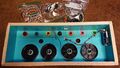
File:Custom Controller Paint Prep Insides.jpg | File:Custom Controller Paint Prep Insides.jpg | ||
File:Custom Controller Paint Done Insides.jpg | File:Custom Controller Paint Done Insides.jpg | ||
| Line 627: | Line 633: | ||
When finished, remove the painter’s tape and the protective craft paper. | When finished, remove the painter’s tape and the protective craft paper. | ||
==Outside Job== | ===Outside Job=== | ||
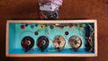
[[File:Custom Controller Paint Done Outsides.jpg|right|300px]] | [[File:Custom Controller Paint Done Outsides.jpg|right|300px]] | ||
| Line 633: | Line 639: | ||
Basically the same deal with doing the insides. Use painter’s tape and craft paper to protect the inside paint job if you painted the insides. Remember that you also want to hit the sides this time (except for the long side pieces). | Basically the same deal with doing the insides. Use painter’s tape and craft paper to protect the inside paint job if you painted the insides. Remember that you also want to hit the sides this time (except for the long side pieces). | ||
=Final Preparation= | ==Final Preparation== | ||
Everything in the section can be done while you are waiting for the paint process to complete. | Everything in the section can be done while you are waiting for the paint process to complete. | ||
==Button Decals== | ===Button Decals=== | ||
[[File:Custom Controller Button Decals.png|right|300px]] | |||
The following decals were found at meenia.jp. Unfortunately, only the decals for the buttons were done as the target was an arcade controller. You’ll need to print them on decal paper using an inkjet printer. Use the best quality setting to get the most vivid results. Print at 300dpi for 100mm buttons and at 500dpi for 60mm buttons. Allow time for the ink to dry. Apply 3 coats of acrylic clear coat, and allow to dry. Cut out the decals with a hobby knife. Exercise patience and go slowly to get the cleanest circular cut that you can. | The following decals were found at [http://meenia.jp/diy/controller/miku-pd/pd-02 meenia.jp]. Unfortunately, only the decals for the buttons were done as the target was an arcade controller. You’ll need to print them on decal paper using an inkjet printer. Use the best quality setting to get the most vivid results. Print at 300dpi for 100mm buttons and at 500dpi for 60mm buttons. Allow time for the ink to dry. Apply 3 coats of acrylic clear coat, and allow to dry. Cut out the decals with a hobby knife. Exercise patience and go slowly to get the cleanest circular cut that you can. | ||
Prep the game buttons by completely disassembling them. Place the cut-out decals in water to separate the decals from the paper backing. Again, exercise patience. Once you have the decals separated from the backing, place on the decal plate, aligning the arrows with one of the notches. | Prep the game buttons by completely disassembling them. Place the cut-out decals in water to separate the decals from the paper backing. Again, exercise patience. Once you have the decals separated from the backing, place on the decal plate, aligning the arrows with one of the notches. | ||
==Dupont-to-Disconnect Dongle== | ===Dupont-to-Disconnect Dongle=== | ||
[[File:Disconnect to Dupont Dongle.jpg|right|300px]] | |||
Take one color of each wire from your collection of 0.110″ (the small one) spade connectors. Cut 12in/30.5cm (for arcade controllers) or 9in/23cm (for home controllers) from the non-connector end. Strip the wire on each end and attach a female dupont connector on one end and a female 0.25″ spade connector on the other. (You can find plenty of videos on YouTube on how to crimp these connectors.) Use a multimeter to verify your crimps have actually made connections. | Take one color of each wire from your collection of 0.110″ (the small one) spade connectors. Cut 12in/30.5cm (for arcade controllers) or 9in/23cm (for home controllers) from the non-connector end. Strip the wire on each end and attach a female dupont connector on one end and a female 0.25″ spade connector on the other. (You can find plenty of videos on YouTube on how to crimp these connectors.) Use a multimeter to verify your crimps have actually made connections. | ||
==Joystick-to-Disconnect Dongle== | ===Joystick-to-Disconnect Dongle=== | ||
[[File:Disconnect to Joystick Dongle.jpg|right|300px]] | |||
Cut off another 6in/15cm (for arcade controllers) or 3in/7.5cm (for home controllers) from the non-connector end of the same wires you just cut from. Strip your wires from both ends, then use 1½”/4cm of heat shrink to help you segregate wires first per potentiometer then per joystick. You then want to crimp the wires into male spade connectors for connection into the harness coming from the Fighting Board. You will have to join the 4 VCC wires together into one spade connector. Same goes for ground. | Cut off another 6in/15cm (for arcade controllers) or 3in/7.5cm (for home controllers) from the non-connector end of the same wires you just cut from. Strip your wires from both ends, then use 1½”/4cm of heat shrink to help you segregate wires first per potentiometer then per joystick. You then want to crimp the wires into male spade connectors for connection into the harness coming from the Fighting Board. You will have to join the 4 VCC wires together into one spade connector. Same goes for ground. | ||
| Line 653: | Line 665: | ||
To conserve wire, I equate orange with white and black with grey. This way you’re not running out of orange and black wire. | To conserve wire, I equate orange with white and black with grey. This way you’re not running out of orange and black wire. | ||
==Solder to Joysticks== | ===Solder to Joysticks=== | ||
[[File:Joystick Explain.png|right]] | |||
Joystick operation is a lot easier to show than to explain. Referencing the image shown, the following points should make total sense: | Joystick operation is a lot easier to show than to explain. Referencing the image shown, the following points should make total sense: | ||
| Line 662: | Line 676: | ||
* The readout lead is always the lead in the middle. | * The readout lead is always the lead in the middle. | ||
=Begin Assembly= | ==Begin Assembly== | ||
Attach the Fighting board to the side. | <gallery> | ||
File:Assembly Fighting Board.jpg|Attach the Fighting board to the side. | |||
Attach USB Port and DC Jack to side. | File:Assembly USB Inside.jpg|Attach USB Port and DC Jack to side. | ||
File:Assembly USB Outside.jpg|Insert top row buttons. | |||
Insert top row buttons. | File:Assembly All Buttons.jpg|Insert game play buttons. | ||
File:Assembly Wires.jpg|Wire the “game play” buttons. | |||
Insert game play buttons. | </gallery> | ||
==Tada!== | |||
[[File:Assembly Complete Inside.jpg|none|1680px]] | |||
[[File:Assembly Complete Outside.jpg|none|1680px]] | |||
Latest revision as of 15:33, 2 June 2022
History
-
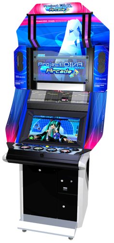 Project DIVA Arcade was initially released in Japan on June 23, 2010.
 -
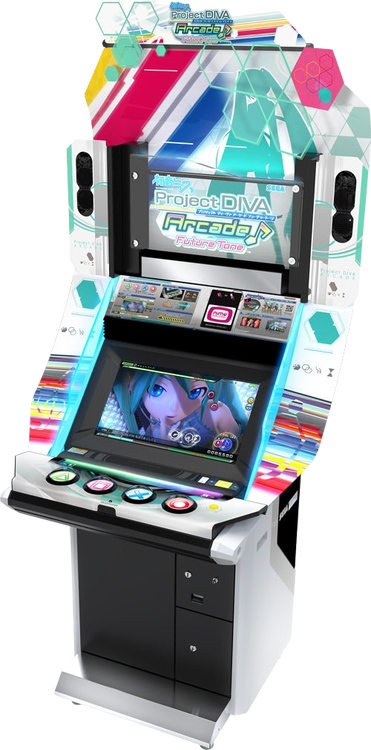 Project DIVA Arcade Future Tone was released November 21, 2013 and introduced the slider.


Project DIVA has a split personality of sorts. Prior to the release of Project DIVA Future Tone on the PlayStation 4, most outside of Asia didn’t know the complete history of the series. Most know about the PlayStation 3 and PlayStation Vita games, as that’s when Sega started porting the series to the west. Before that, few knew that there were PlayStation Portable games that could be imported. But what remained off nearly all westerners’ radars was Project DIVA Arcade. (Mostly for lack of any hope of ever playing it.)
Starting 15 months after the release of the very first Project DIVA on PlayStation Portable, Sega released Project DIVA Arcade. The game play remained relatively the same, with the notable exceptions of Holds and Multi-Notes. The initial HUD of Project DIVA Arcade was the same as found in the PlayStation Portable counterpart. It was later changed to swap the locations of the timing rank and combo counter, and then finally to the timing+count location we know today. Songs were made exclusively for the arcade, and Sega even held Edit Mode contests where winners would get their songs and PVs put into the arcade version.
In addition to that, the PlayStation Portable games also had a PlayStation 3 counterpart called Dreamy Theater. Dreamy Theater contained the exact same songs and PVs found on the PlayStation Portable counterpart, but with assets ported over from the arcade. Nothing can be unlocked within Dreamy Theater -- the user is supposed to play the PlayStation Portable game to unlock everything. The original Dreamy Theater required a constant connection to a PlayStation Portable with game save file from the PlayStation Portable game. Dreamy Theater 2nd and Dreamy Theater Extend changed this to only require a connection once.
Project DIVA has been simultaneously available on portables, home consoles, and in the arcades since 2010. This arcade presence has influenced the home versions and vice versa. Project DIVA 2nd adopted the EXTREME difficulty and introduced the dual-wielding mechanism to deal with the requisite rapid button presses. Project DIVA Arcade: Future Tone introduced sliders after Project DIVA F introduced its scratch notes.
What Does This All Mean?

Project DIVA Arcade aligning the targets with the layout of the buttons. 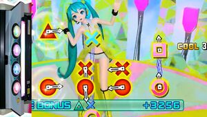
Project DIVA Arcade aligns the targets even when switching to the vertical presentation.


In general, arcade controls are a great way to go with Project DIVA. One common complaint I hear from up-and-coming Project DIVA players is the initial inability to effectively dual-wield the directional pad and game buttons. An arcade-style controller alleviates this learning curve. Outside of that, the home games don’t suffer much more as they have to work with the standard game pads that comes with the console.
But the recent ports of the arcade game are a different story. The port makes no in-game concession to the game pad, and Project DIVA Arcade has some rather jarring mechanics when attempted on a game pad. This isn’t to say they can’t be overcome — hisokee routinely abuses his fingers on a game pad, and I know others that can get PERFECT on 10★ EX EXTREME songs using a game pad. It’s not that it can’t be done, it’s just that I’d argue that it’s a tortuous experience that you may not want to go through.
The most noticeable thing about bringing Project DIVA Arcade home to a game pad is that you lose all positional help. In the arcade, the buttons are laid out in a single row, in the same order as Sony's Dualshock controllers if you go counter-clockwise. When presenting multi-notes to the player, the notes to hit are laid out in the same order on-screen. This makes hitting multi-notes in the arcade relatively simple, compared with having to learn new d-pad + button combos on the Dualshock.
When you get into EXTREME and EX EXTREME, you may find the multi-notes rotated 90° so they can fit a lot of them on the screen at the same time.
On the home side of the equation, there are songs where button presses are fast enough to quickly tire out your thumbs if you try to single-wield the button presses. Using an arcade-like controller for the home games alleviates this stress.
Why Are These Controllers So Expensive?

That depends on what you’re talking about.
If you’re talking about the Project DIVA controllers from HORI, those are limited-run controllers. They’re not that expensive on launch, which makes them prime targets for scalping. Prices are often set to more than double the original sale price, and can be more than quadruple for recently released controllers.
If you’re talking about unofficial controllers, well, the parts are just that expensive. Yes, there’s definitely some inflated markup, but you’ll find their final price is actually somewhere in the middle between parts cost only and parts cost + all the tools you would need to do it yourself.
If you’re looking to make your own controller to spite the high cost of pre-built commercial offerings, you’ll probably be spending more than if you just bought someone else’s controller. But if you’re building your own controller to spite the scalping, you can probably make out.
What Do I Need?
Tools
| Lumber Crayon | 98¢ |
| Use one of these to mark the edges of the wood you buy, so you know which edges are square. | |
| Milwaukee 6ft/2m Tape Measure | $3.97 |
| America doesn't have an arcade scene any more. All the parts will come from outside the US, which means you need to be able to measure in metric. For just under $4, this tape measure can't be beat. | |
| Carpenter Pencil or kit with sharpener | 18¢ - $3.98 |
| You can swing it with a regular pencil, but those are designed for writing on paper and will require frequent re-sharpening and often break when writing on wood. If you don't already have a sharpener for carpenter pencils, you might as well get the kit that includes that. You won't need 10 pencils for this project (1 will more than suffice) but they're basically free when compared to the cost of buying the sharpener separately. | |
| Irwin Speedbor ⅝" Spade Drill Bit | $4.48 |
| Used to drill holes for 16mm buttons. | |
| Irwin Speedbor 15⁄16" Spade Drill Bit | $4.98 |
| Used to drill holes for 24mm buttons. | |
| Irwin Speedbor 1" Spade Drill Bit | $5.18 |
| Used to drill the hole for the Brook USB & headphones jack plate. | |
| Irwin Speedbor 1⅛" Spade Drill Bit | $5.98 |
| Used to drill holes for 30mm buttons. | |
| Multimeter | $7.95 |
| Used to test your dupont connections. | |
| Butt Splice (Quick Connect) Tool | $9.18 |
| Used to make extra connections. | |
| Black and Decker Alkaline Screw Driver at Lowes or Home Depot | $10.15 |
| This screwdriver is good enough to save you from having to torque 24 screws but not powerful enough to overtorque and cause stripping. | |
| Step Drill Bit | $10.99 |
| Used to drill the holes for the joystcks. | |
| T-Square | $12.28 |
| Make straight lines that square with a side. | |
| Dupont Crimp Tool | $15.99 |
| The joystick connection to the board requires an 8-pin female dupont connector. You're probably more familiar with the connector type than its name -- IDE/PATA and jumpers are forms of dupont connections. You probably don't have the tool or connectors unless you also work on hobby boards like the Raspberry Pi. You can save a few dollars by buying a kit with both the crimp tool and a set of connectors. | |
| Drill Bit Set -- Craftsman or DeWalt | $14.98 |
| Used mostly to drill pilot holes. | |
| Hyper Tough Rotary Tool | $17.83 |
| The best price for the tool itself, even though it comes in a kit with parts. Do yourself a favor and throw those parts away. They're cheap and tend to break, which is dangerous when it occurs at 35,000 RPM. | |
| Lenox 2" Hole Saw | $16.98 |
| Used to drill the holes for 60mm buttons. | |
| Lenox 3½" Hole Saw | $24.98 |
| Used to drill the holes for 100mm buttons. | |
| Black & Decker Sheet Sander | $29.98 |
| Finish your edges and give yourself smooth surfaces for painting. | |
| Soldering Iron | $29.99 |
| You can try to use cheap department store soldering irons, but you're going to have a bad time. Spend a little more to pick up a decent soldering station. Only the joysticks require any soldering, but you may find yourself needing to splice wires as well. | |
| Black & Decker Drill | $34.98 |
| Don't cheap out on the drill. When dealing with harder woods, cheap off-brand drills can burn themselves out. Stick with name brands on this tool. | |
| Dremel Accessory Kit | $34.98 |
| Get the sanding and cutting tools you'll need for your rotary tool. | |
| Shop-Vac 2½ Gallon Shop Vacuum | $39.98 |
| Clean up your mess! As a bonus, some tools are designed to fit the Shop-Vac hose so you can use them dust-free. | |
| Ryobi Miter Saw | $99.00 |
| Used to cut the sides of the controller. | |
| Ryobi Table Saw | $119.00 |
| Used to cut the top and bottom pieces of the controller. | |
| TOTAL | up to $532.33 |
Parts
| 16pc ¾" #6 wood screws | $1.28 |
| Used to secure the bottom of the controller when using ¼" thick wood. | |
| 14pc 1" #6 wood screws | $1.28 |
| Used to secure the top of the controller. | |
| 8pc 1½" #6 wood screws | $1.28 |
| Used to secure the left and right sides to the top and bottom sides. | |
| 10pc M2 8mm screws | $1.79 |
| Used to secure the DC step-up converter. | |
| 10pc M2 20mm screw | $2.89 |
| Used to secure the joysticks | |
| 200pc M2 1mm washer | $5.99 |
| Used to space the DC step-up converter from its mount. | |
| Solder | $8.59 |
| Used to attach wires to the leads on the joysticks. | |
| 20pc Anti-skid pads | $8.99 |
| Nothing worse than your controller sliding around while you're trying to play. | |
| Dupont Connectors | $10.99 |
| Used to connect the wires from the joysticks to the Brook Fighting Board. | |
| 22pc Multi-Grit Sandpaper Pack | $11.98 |
| Used to sand down your controller. The multi-pack is cheaper than buying separate grit packs. | |
| ¼" x 2' x 4' lauan plywood | $6.91 |
| Used to make the bottom of the controller if you're willing to pay a little extra to trim some height off of your controller. | |
| 1" x 3" x 6' (actual ¾" x 2½" x 6') red oak | $11.98 |
| Used to make the sides of the controller. If using Micro-Leaf switches, 2½" will be just short and you'll need to get the 4" (actual 3½") version instead. | |
| ½" x 2' x 4' oak plywood | $26.98 |
| Used to make the top of the controller, and optionally the bottom if you want to save money. | |
| TOTAL | up to $100.93 |
Paint
Painting is optional and purely cosmetic, but it can lend a professional look to your work. The main problem is time — you must wait for the paint to cure, and you definitely want to wet sand spray paint to get a smooth-as-possible finish.
Spray Paint
| Duck Clean Release Painter's Tape | $2.97 |
| Rust-oleum Satin Seaside or Sping Green (Miku colors) | $3.96 |
| Rust-oleum Satin Blossom White | $3.96 |
| Rust-oleum Satin Crayon Black | $3.96 |
| Rust-oleum Clear Coat | $3.96 |
| 3M SandBlaster Sanding Sponge - 180 | $3.97 |
| 3M SandBlaster Sanding Sponge - 320 | $3.97 |
| Craft Paper | $4.68 |
| TOTAL | $31.43 |
Cold Weather Supplements
Spray paint works best outdoors in warm weather. If you don’t have that luxury, you’ll need to simulate it. The best option is to utilize a ventilated upstairs room or finished attic. Place the parts to be spray painted near the ventilation point. Use heat lamps to heat up the paint, and let the ventilation pull the air across those parts.
| 2x GE 250-Watt R40 Heat Lamp Incandescent Light Bulb | $19.94 |
| 2x ProTorch Incandescent Clamped Work Light | $27.96 |
| TOTAL | $48.90 |
Game Control Parts
Controller Board
| 30-connection 22 AWG .110" Ground Daisy Chain Wire | $4.45 |
| 16pc 22 AWG Wire with .110" Quick Disconnect | $7.25 |
| 30-connection 22 AWG .187" Ground Daisy Chain Wire | $4.45 |
| 16pc 22 AWG Wire with .187" Quick Disconnect | $7.25 |
| 30pc Cable Clips | $7.86 |
| 10pc DC Step-Up Converter | $7.99 |
| PCScrew Assortment Kit (for standoffs & standoff screws) | $8.99 |
| 0.25" Male/Female Quick Disconnects | $9.99 |
| Brook PS4+ Fighting Board at Focus Attack or Amazon | $64.95 |
| TOTAL | $133.17 |
Button Options (for L2/L1/Select/Home/Start/R1/R2)
While the links aren’t the only options, they’re the ones that I feel make the most sense. Sanwa is the brand used in Project DIVA Arcade. Other brands are available, but they don’t offer any cost savings. On the off-brand side, color choice is limited and often come in bundles that mostly make no sense for this project. Seimitsu makes similar buttons — they only come in 7 colors but they might all that’s in stock when you go to shop.
| Size | Each | ×7 |
|---|---|---|
| Generic 16mm (choice of 4 colors) | 95¢ | $6.65 |
| 10pc EG Starts 24mm (black only) | $9.99 | $9.99 |
| 10pc EG Starts 30mm (black only) | $9.99 | $9.99 |
| Sanwa 24mm (11 colors) | $2.25 | $15.75 |
| Seimitsu 24mm (7 colors) | $2.25 | $15.75 |
| Sanwa 30mm (13 colors) | $2.45 | $17.15 |
EG Starts 100mm Push Buttons (PDFT/PDM39/PDMM)
The EG Starts 100mm buttons come with springs that are FAR too heavy. I wouldn’t doubt if the spring was meant for joysticks, which are usually used for tension and provide a lot more resistance than button springs. You will need to shell out for set of button springs.
| 10pc 200g OBSA-SP spring | $7.18 |
| 4x EG Starts 100mm buttons | $39.96 |
| TOTAL | $47.14 |
EG Starts 60mm Push Buttons (All PS3 games + PDX)
Again, EG Starts’ buttons come with springs that are FAR too heavy.
| 10pc 200g OBSA-SP spring | $7.18 |
| 2x 5pc EGStarts 60mm buttons | $20.68 |
| TOTAL | $27.86 |
Sanwa 100mm Push Buttons (PDFT/PDM39/PDMM)
The Sanwa buttons come with 200g springs, but the bulb is sold separately.
| 4x SWA-LED SANWA LED Bulb | $33.70 |
| 4x Sanwa OBSA-100UMQ 100mm buttons | $137.72 |
| TOTAL | $171.42 |
Switch Options
In my experience, the OMRON D2MV-01-1C1 is the best option when going with EG Starts buttons. There’s no actuation bump, which is the same experience you get with the photo sensors in the arcade.
The Micro-Leaf switches might look like a good compromise, but they’re a total PITA. They don’t quite fit the EG Starts 100mm buttons — you will have to sand down and finesse the switches into place. You also have to manually bend the leaf to make proper contact. They make for an excellent arcade-like experience with a negligible actuation bump, but the manual intervention needed (with inevitable human error) is a huge deterrent.
The cheapest acceptable option is the GroovyGamer SST micro switches. The actuation bump is barely noticeable. Does it hamper game play? Not in the slightest. But the OMRONs provide a closer-to-arcade experience.
| Switch Type | Installation | Actuation Bump | Cost ×4 | Cost ×8 |
|---|---|---|---|---|
| Groovy SST | snap-in | barely noticeable | $3.56 | $7.12 |
| Micro-Leaf | PITA | negligible | $11.00 | $22.00 |
| OMRON D2MV-01-1C1 | snap-in | none | $17.04 | $34.08 |
| LHSXF-H wire harness | - | - | $11.99 | $23.98 |
| OBSA-LHSXF | twist-on | none | $122.16 | $244.32 |
Ultimate Arcade Experience
If you want an authentic arcade experience, you need to use Sanwa 100mm pushbuttons with the Sanwa optical switch — the Sanwa optical switch will NOT fit the EG Starts 100mm pushbuttons. This list supersedes the Generic 100mm Pushbuttons, Sanwa 100mm Pushbutons, and Switch Options sections.
| 4x OBSA-LHSXF Wire Harness | $11.99 |
| 4x SWA-LED Sanwa LED Bulb | $33.70 |
| 4x Sanwa OBSA-100UMQ 100mm pushbuttons | $137.72 |
| 4x Sanwa OSBSA-LHSXF optical switch | $122.16 |
| TOTAL | $305.57 |
Button Graphics
| Squeegee & Hobby Knife Set | $6.99 |
| Krylon Clear Acryllic Coating | $8.65 |
| Inkjet Decal Paper | $9.78 |
| TOTAL | $25.42 |
Slider
While people have made touch sliders for Project DIVA, no one has marketed it as a product you can simply add to your own controller.
Some people have made a row of buttons to replace the slider, but this solution is limited and jarring when coming from the arcade. Your hands have to go to specific locations to hit the direction you want instead of just heading for a touch bar and sliding in whatever direction you need to. You also need to take care with how you assign these buttons — they’re typically assigned to the directional pad and simultaneous opposite cardinal directions (Left + Right and Up + Down) are normally filtered.
I’ve found the better solution to the slider dilemma is to use joysticks. You still have to train you hands to head for specific locations, but you can now choose from two locations that can each serve either direction, rather than the direction of the slide dictating where your hands need to go.
One thing to watch out for: You want the R4 model which has a 10K potentiometers. The R2 version has 5K potentiometers. A lot of Amazon listings combine the two and then say “5K, 10K available on request” in the description.
| 2x JH-D202X-R4 Analog Joysticks (Arcade) | $23.08 |
What’s the Plan?
-
 Project DIVA Arcade
 -
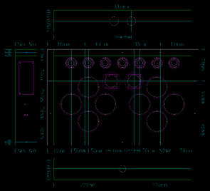 Project DIVA Home


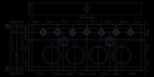
I created the Arcade controller by referencing the Project Diva FT/CT Arcade Controller Instructable. I analyzed tomtortoise’s CAD file for the basics, like the distance between each button’s center point. I replaced the slider buttons with joysticks for a closer-to-arcade feel. And I removed the start button being to the right of ⭕ because it risks an accidental pause on PS4 and Switch.
The Home controller is a modification of the Arcade controller. The left and right groups of buttons maintain the same relative distance from each other on the diagonal as the Arcade controller does on the horizontal, shrunk in scale from 100mm to 60mm. The four buttons that line up on the horizontal are equidistant from each other, though that distance is not and can not be to scale with the Arcade controller while also maintaining the scaled distance on the diagonal. I went with a squared diamond over the skinny diamond of the HORI Project DIVA F (full-sized non-mini) Controller as it’s closer to how the buttons and d-pad are laid out on Sony’s DualShock controllers.
Cut the Top & Bottom Pieces


Take your plywood and cut your top and bottom pieces. Remember that you want to cut up against the pencil lines. If your line completely disappears you’re probably cutting the piece short. If you’re using a table saw, it’s relatively easy to cut longer-than-needed, check with your measuring tape, and then adjust and re-cut if needed. Once you cut you can't glue it back on, so too long is better than too short.
Draw Guidelines to Obtain the Center Points

Follow the appropriate plan to find your center points. These points will be used to drill the holes you need to place the buttons. Use your T-Square against the square sides to keep your lines at 90°. Use a punch tool or sacrificial small Phillips head screw driver to set drill points.
Drill the Holes

This is where you regret living in the United States if you live in United States. The buttons require a hole measured in millimeters, but your tools are all measured in fractions of an inch.
| Button Size | Target Hole Size | Closest fractional | Resulting hole size | Requires sanding? |
|---|---|---|---|---|
| 16mm | 16.0mm | ⅝in | 15.875mm | no |
| 24mm | 23.6mm | 15⁄16in | 23.8125mm | no |
| 30mm | 29.5mm | 1⅛in | 28.575mm | yes |
Make sure you are using scrap wood underneath as this seems to prevent splintering. Allowing yourself to punch right through can lead to splinters over 1 inch (25mm) long.
Game Play Buttons

Again, make sure you have scrap wood underneath to prevent splintering when you break through to the other side.
When you’re done drilling the 100mm holes, you will need to break out your rotary tool to sand a notch at the top and bottom of the holes. Your guidelines should show you where this notch needs to go. The 60mm buttons do not have an alignment notch.
Joysticks

Simply drill the hole as big as you can. Drill a pilot hole from the back side (where you made your marks) and then flip the piece face-up to drill from the front. Drill down until the top of the step drill bit is level with the face of the controller board. The slight angle of the resulting hole is actually desirable considering this is a hole for a joystick.
The screws that come with the joysticks are not long enough for any material thicker than ¼ inch. You’ll need replacement M2 screws that are 20mm long.
To drill the mounting holes, use the retention ring and T-square. Keep the screw holes of the retention ring as square as you can, but it doesn’t have to be exact. Project DIVA Arcade only cares about left and right movement, and F1/F2/X only care that the stick moves. Drill one hole, screw into it, and repeat.
Cut the Sides
Cut your short (left and right) sides to the full length of the side, then cut your long (front and back) sides to fit. This arrangement is made so that the screws are only visible from the sides.
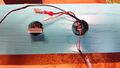
Backside USB Face Plate

Drill a 1″ hole smack dab in the middle of the back side for the USB face plate. NOTE: The picture shows the older design that used a DC input jack to power the LEDs. You can use a DC step-up converter to turn the 5V DC from USB into 12V for the lamps, negating the need for a separate DC input jack.
Fighting Board Standoffs
Despite it being in the plans, there really isn’t a plan for this. The line 40mm down from the top is a suggestion — it doesn’t have to be exact. The same goes for centering the board — human eyeballs are good enough as it really doesn’t have to be exact. You can take the circuit board, lay it on the wood, and mark drill holes for each of the four corners. Use a 7⁄64” drill bit to drill a pilot hole for the standoffs. Getting the standoffs to screw into the wood might take some effort when using oak. An electronics screwdriver set or even a small pliers will help.
Preliminary Assembly
If this was being done by machine, we could make some assumptions. But we’ve had human error involved this entire time, and will continue to have human error throughout. So it’s best not to assume anything and take things one step at a time.
Screw Holes
For #6 wood screws in oak, use a 7⁄64” bit for the pilot hole. This is larger than normal because the normal pilot hole size will net you broken screws.
Fasten the Sides Together

Drill your four pilot holes through the short side first. The holes should be ⅜” from the front and from the back, and smack dab in the middle (1¼”) top-to-bottom.
Once that is done, line up your first corner as flush as possible and continue drilling that one pilot hole. Fasten with a 1½” #6 wood screw and move on to the next corner. The end result isn’t going to be perfect, but it’s going to be a heck of a lot close than if you tried drilling without the guidance of your original pilot holes.
Fasten the Top to the Sides

Drill pilot holes in the top piece according to plan. All screws are placed ⅜” from the edge.
Arcade Controller
Short Sides: Two holes at 80mm marks. Long Sides: Three holes at 150mm marks.
Home Controller
Short Sides: Two holes 93mm from the top and bottom. Long Sides: Three holes at 110mm marks.
Fasten the Bottom to the Sides

All screws are placed ⅜” from the edge.
Arcade Controller
Short Sides: Three holes at the very top, bottom, and middle.
Long Sides: Exactly speaking, you want two more screws 193.65mm apart. This would give you four screws along the bottom at 9.525mm, 203.175mm, 396.825mm. and 590.475mm. Get an estimation of the middle two measurements by rounding and measuring from both sides.
Home Controller
Short Sides: Three holes at the very top, bottom, and middle.
Long Sides: Exactly speaking, you want four screws along the long edges at 9.525mm, 156.191mm, 302.858mm, and 430.475mm. Get an estimation of the middle two measurements by rounding and measuring from both sides.
Sand It Down
Use your palm sander and sand everything down. This is where you compensate for your human error as much as possible. Try to make everything as flush as possible within the first two passes. The final two passes should be used to make the wood as smooth as possible.
Start with the front and back sides. Then remove the screws from one of the short sides and sand that side down. Replace the screws when done. Repeat for the the other side. Remove the top and sand both the facing and under side. Do the same for the bottom piece.
Paint
This is completely up to you. You can use whichever colors you want. You can paint just the outside, or you can paint the insides as well. Just know that this part requires patience and will add days to your project.
If you decide to paint, protect your workstation. Apply 3 coats of paint. Allow each coat to dry for at least 8 hours. Sand with a wet sanding sponge before applying the next coat, taking care to wipe down the paint job and let dry for an hour. Apply 3 coats of clear coat, and let sit for 48 hours.
Inside Job


If you want to paint the inside of the controller, start with it first. Use your painter’s tape and craft paper to keep over-spray from getting on the outsides. In general, you don’t want to get any paint on the edges, either.
When finished, remove the painter’s tape and the protective craft paper.
Outside Job

Basically the same deal with doing the insides. Use painter’s tape and craft paper to protect the inside paint job if you painted the insides. Remember that you also want to hit the sides this time (except for the long side pieces).
Final Preparation
Everything in the section can be done while you are waiting for the paint process to complete.
Button Decals

The following decals were found at meenia.jp. Unfortunately, only the decals for the buttons were done as the target was an arcade controller. You’ll need to print them on decal paper using an inkjet printer. Use the best quality setting to get the most vivid results. Print at 300dpi for 100mm buttons and at 500dpi for 60mm buttons. Allow time for the ink to dry. Apply 3 coats of acrylic clear coat, and allow to dry. Cut out the decals with a hobby knife. Exercise patience and go slowly to get the cleanest circular cut that you can.
Prep the game buttons by completely disassembling them. Place the cut-out decals in water to separate the decals from the paper backing. Again, exercise patience. Once you have the decals separated from the backing, place on the decal plate, aligning the arrows with one of the notches.
Dupont-to-Disconnect Dongle

Take one color of each wire from your collection of 0.110″ (the small one) spade connectors. Cut 12in/30.5cm (for arcade controllers) or 9in/23cm (for home controllers) from the non-connector end. Strip the wire on each end and attach a female dupont connector on one end and a female 0.25″ spade connector on the other. (You can find plenty of videos on YouTube on how to crimp these connectors.) Use a multimeter to verify your crimps have actually made connections.
Joystick-to-Disconnect Dongle

Cut off another 6in/15cm (for arcade controllers) or 3in/7.5cm (for home controllers) from the non-connector end of the same wires you just cut from. Strip your wires from both ends, then use 1½”/4cm of heat shrink to help you segregate wires first per potentiometer then per joystick. You then want to crimp the wires into male spade connectors for connection into the harness coming from the Fighting Board. You will have to join the 4 VCC wires together into one spade connector. Same goes for ground.
To conserve wire, I equate orange with white and black with grey. This way you’re not running out of orange and black wire.
Solder to Joysticks

Joystick operation is a lot easier to show than to explain. Referencing the image shown, the following points should make total sense:
- The pot running parallel to an axis controls the axis.
- The VCC lead aligns with the positive side of the axis.
- The ground lead aligns with the negative side of the axis.
- The readout lead is always the lead in the middle.
Begin Assembly
-
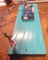 Attach the Fighting board to the side.
 -
 Attach USB Port and DC Jack to side.
 -
 Insert top row buttons.
 -
 Insert game play buttons.
 -
 Wire the “game play” buttons.


Tada!

